A Quick Look at a Breadboard
A breadboard helps us make quick connections to try out circuit ideas.
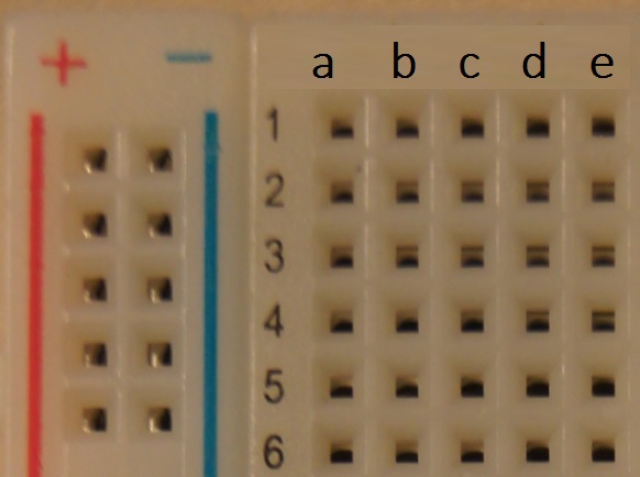
Down the left hand side of the board are two busses, one labeled + for positive and one with a - for negative. Each bus is just a solid strip of conductive material with access points that we can use to plug jumper wires in. The labels just help us remember where we have plugged our positive and negative wires.
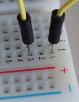
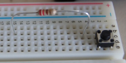
To the right of the busses are nodes which are labeled with numbers. Each node is also a strip of conductive material. They are like short busses. The nodes on the breadboard are also labeled. On this breadboard I have nodes 1 through 30 with connection points labeled a, b, c, d, and e on one side and nodes 1 through 30 with connection points labeled f, g, h, i, and j on the other side. A channel down the center of the board seperates the two sets of nodes. We can connect two nodes with a jumper wire plugged into any connection port on each node. Here I have connected node 1 and 3 on the right side of my breadboard. I used connection port j on each node but any two points would create the same connection as long as one is on each node.
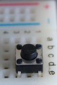
Many components can be plugged directly into the breadboard. I have connected nodes 1 and 3 with a button pushed into node 1, points c and e and node 3 points c and e. When the button is depressed a connection is made and the two nodes are connected.
Resistors can also be plugged directly into the breadboard. What two nodes are connected by this resistor? It connects nodes 5 and 15. Notice that the resistor is not connected to the button. The button is connected to node 3 at point c and the resistor is connected to node 5 at point c but there is no connection between nodes 3 and 5.
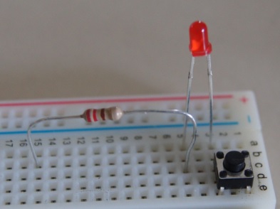
I can connect the button and the resistor with an LED (light emmiting diode) that connects node 3 and 5.
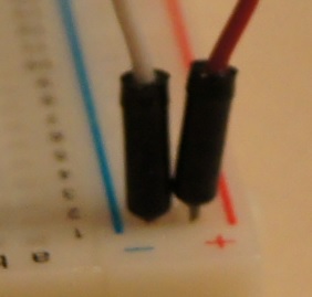
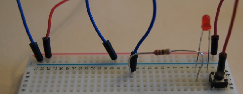
Now all we need is current. One thing to remember is that current will only flow through a diode in one direction. To make this LED light up I have connected a 3 volt power supply to the positive and negative bus and have connected the positive bus to node 1 with a red jumper wire and the negative bus to node 15 with a blue jumer wire.
When the button is up the circuit is open (not connected) between nodes 1 and 3.
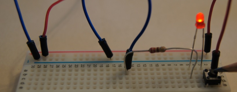
When the button is down the circuit is closed (connected) between nodes 1 and 3.
- Supplies
- Breadboard
- Buttons
- Jumper Wires
- Red LEDs